Specification of analysis control parameters.
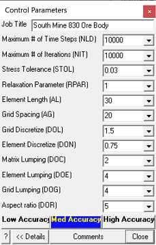
Job Title - specifies a descriptive project title.
Maximum # of Time Steps (NLD) - specifies the maximum number of steps that will be used during analysis. This parameter is only relevant if you are conducting a non-linear creep analysis
where this limits the actual number of time steps.
If this parameter is exceeded, the program stops and the user is prompted for instructions on how to proceed. This parameter can be modified during solution.
Unless the user has some special reason for limiting the number of time steps this parameter should be set to an arbitrarily large number.
Maximum # of Iterations (NIT) - specifies the maximum number of iterations that will used during matrix solution.
If this parameter is exceeded, the program stops and the user is prompted for instructions on how to proceed. This parameter can be modified during solution.
Unless the user has some special reason for limiting the number of time steps this parameter should be set to an arbitrarily large number.
Stress Tolerance (STOL) - specifies the required accuracy of the matrix solution.
During matrix solution the accuracy is successively improved with each iteration. When the maximum stress error falls below this value the matrix can be considered to be solved.
The suggested value for the parameter is 0.1% of the far field stress state at the depth of interest. STOL should be specified in the same units as the far field stress state (e.g. MPa or psi).
Relaxation Parameter (RPAR) - specifies the maximum relaxation value that will be used during matrix solution.
During matrix solution the program continuously modifies the relaxation parameter in an attempt to obtain convergence with as few as possible iterations. This parameter limits the maximum value that will be used.
The value of 1.2 is recommended for well-conditioned problems. For poorly conditioned problems a value of 0.8 should be used.
Element Length (AL) - specifies the minimum element length.
During the discretization process all model surfaces (surfaces of FF blocks and DD planes) are subdivided into boundary elements with side length
Lelem = Delem/DON
where Delem is determined by Map3D as the smallest distance between adjacent model surfaces. Since at some locations the distance Delem may be zero, the minimum element side length AL must be specified.
AL should be set equal to twice the smallest pillar or stope width. The same units used to specify the coordinates should be used (e.g. metres or feet).
Once discretization is complete, the distance Delem can be plotted using
![]() Plot > Miscellaneous > Delem distance to nearest element on surfaces.
Plot > Miscellaneous > Delem distance to nearest element on surfaces.
Note that if desired, this behaviour can be overridden on an element by element basis by specifying the maximum width for each element
![]() CAD > Edit > Entity Properties > Maximum Width
CAD > Edit > Entity Properties > Maximum Width
This allows users to force fine uniform discretization on surfaces in areas where there are no grid planes.
Grid Spacing (AG) - specifies the minimum grid spacing.
During the discretization process all field point grids and model surfaces are subdivided into elements with side length
Lgrid = Dgrid/DOL
where Dgrid is determined by Map3D as the smallest distance between model surfaces and grid planes. Since at some locations the distance Dgrid may be zero, the minimum grid spacing AG must be specified. This same process is used to discretize model surfaces (surfaces of FF blocks and DD planes) that are near field point grids.
AG should be set equal to the smallest dimension of interest. For example if the user needs to see the stress distribution across a 2m wide pillar, a value for AG of 0.5 would give sufficient number of field points for accurate contouring. The same units used to specify the coordinates should be used (e.g. metres or feet).
Once discretization is complete, the distance Dgrid can be plotted on model surfaces using
![]() Plot > Surface Components > Dgird distance to nearest grid
Plot > Surface Components > Dgird distance to nearest grid
or on grids using
![]() Plot > Miscellaneous > Delem distance to nearest element on grids.
Plot > Miscellaneous > Delem distance to nearest element on grids.
Note that if desired, this behaviour can be overridden on a grid by grid basis by specifying the maximum spacing for each grid
![]() CAD > Edit > Entity Properties > Maximum Width
CAD > Edit > Entity Properties > Maximum Width
This allows users to force fine uniform discretization on grids.
Grid Discretize (DOL) - specifies the desired distance to element length ratio used to determine the grid spacing from
Lgrid = Dgrid/DOL
where Dgrid is determined by Map3D as the smallest distance between model surfaces and grid planes.
A value for DOL of 1.0 is generally adequate and can be expected to provide solutions with 10-20% error. If higher accuracy is required a value for DOL of 2.0 should give 5-10% error. Use a value of 4.0 for less than 5% error. Although higher values of DOL results in generation of more boundary elements and hence longer run times, this is necessary to obtain increased accuracy.
Once discretization is complete, the ratio of Dgrid/Lelem can be plotted on model surfaces using
![]() Plot > Miscellaneous > Dgrid/Lelem DOL ratio on surfaces
Plot > Miscellaneous > Dgrid/Lelem DOL ratio on surfaces
or the ratio of Dgrid/Lgrid on grids using
![]() Plot > Miscellaneous > Dgrid/Lgrid DOL ratio on grids.
Plot > Miscellaneous > Dgrid/Lgrid DOL ratio on grids.
Element Discretize (DON) - specifies the desired distance to element length ratio used to determine the element side length
Lelem = Delem/DON
where Delem represents the distance to the nearest model surface.
A value for DON of 0.5 is generally adequate for all problems except those with very narrow excavations or pillars. In this latter case a value for DON of 1.0 is recommended. Although higher values of DON results in generation of more boundary elements and hence longer run times, this is necessary to obtain a well conditioned solvable problem for very narrow excavations or pillars.
Once discretization is complete, the ratio of Delem/Lelem can be plotted using
![]() Plot > Miscellaneous > Delem/Lelem DON ratio on surfaces.
Plot > Miscellaneous > Delem/Lelem DON ratio on surfaces.
Matrix Lumping (DOC) - specifies the desired distance to element length ratio. During matrix assembly, all elements that fit within the dimension
Delem/DOC
will be lumped together. Delem represents the distance to the nearest model surface.
Just as for DOL, a value for DOC of 1.0 is generally adequate and can be expected to provide solutions with 10-20% error. If higher accuracy is required a value for DOC of 2.0 should give 5-10% error. Use a value of 4.0 for less than 5% error. Although higher values of DOC result in larger coefficient matricies and hence longer run times, this is necessary to obtain increased accuracy.
Once discretization is complete, the distance Delem can be plotted using
![]() Plot > Miscellaneous > Delem distance to nearest element on surfaces.
Plot > Miscellaneous > Delem distance to nearest element on surfaces.
Element Lumping (DOE) - specifies the desired distance to element length ratio. During grid assembly, all elements that fit within the dimension
Dgrid/DOE
will be lumped together. Dgrid represents the distance to the nearest field point grid surface.
A value for DOE of 2.0 is generally adequate and can be expected to provide solutions with 10-20% error. If higher accuracy is required a value for DOE of 4.0 should give 5-10% error. Use a value of 8.0 for less than 5% error. Although higher values of DOE result in longer run times, this is necessary to obtain increased accuracy.
Once discretization is complete, the distance Dgrid can be plotted on grids using
![]() Plot > Miscellaneous > Delem distance to nearest element on grids.
Plot > Miscellaneous > Delem distance to nearest element on grids.
Grid Lumping (DOG) - specifies the desired distance to element length ratio. During grid assembly, all grid points that fit within the dimension
Dgrid/DOG
will be lumped together. Dgrid represents the distance to the nearest field point grid surface.
A value for DOG of 2.0 is generally adequate and can be expected to provide solutions with 10-20% error. If higher accuracy is required a value for DOG of 4.0 should give 5-10% error. Use a value of 8.0 for less than 5% error. Although higher values of DOG result in longer run times, this is necessary to obtain increased accuracy.
Once discretization is complete, the distance Dgrid can be plotted on grids using
![]() Plot > Miscellaneous > Delem distance to nearest element on grids.
Plot > Miscellaneous > Delem distance to nearest element on grids.
Aspect Ratio (DOR) - specifies the desired element aspect ratio. A value for DOR of 5.0 is recommended for all problems except where the user wants narrow elements subdivided into more uniform shapes.
![]() Sets DON=0.5, DOL=DOC=1, DOE=DOG=2 for 10-20% error.
Sets DON=0.5, DOL=DOC=1, DOE=DOG=2 for 10-20% error.
![]() Sets DON=0.5, DOL=DOC=2, DOE=DOG=4 for 5-10% error.
Sets DON=0.5, DOL=DOC=2, DOE=DOG=4 for 5-10% error.
![]() Sets DON=1, DOL=DOC=4, DOE=DOG=8 for < 5% error.
Sets DON=1, DOL=DOC=4, DOE=DOG=8 for < 5% error.
Comments - allows you to specify comments to be saved with the run.
Summary:
STOL should be set equal to 0.1% of the far field stress state at the depth of interest. Use the same units as the far field stress state (e.g. MPa or psi).
AL should be set equal to twice the smallest pillar or stope width. Use the same units used to specify the coordinates (e.g. metres or feet).
AG should be set equal to the smallest dimension of interest. Use the same units used to specify the coordinates (e.g. metres or feet).
Elements are discretized to a side length that is the smaller of Delem/DON and Dgrid/DOL, such that it cannot be less than AL and cannot be larger than the maximum width.
Grid are discretized to a spacing is determined from Dgrid/DOL such that is cannot be less than AG and cannot be larger than the maximum spacing.
During matrix assembly, all elements that fit within the dimension Delem/DOC will be lumped together.
During grid assembly, all elements that fit within the dimension Dgrid/DOE will be lumped together.
During grid assembly, all grid points that fit within the dimension Dgrid/DOG will be lumped together.
Notes:
For a more detailed discussion on discretization and lumping refer to