![]() Plot > Surface Components > ERR
Plot > Surface Components > ERR
|
|
Top Previous Next |
|
Calculate energy release rate. This component can be accessed via the Strength Factor Components toolbar as follows:
This toolbar can be changed to a vertical orientation by dragging is against either the right or left hand edge of the main window. It can be changed back to a horizontal orientation by dragging is against either the top or bottom edge of the main window.
Selecting the
This routine enables the user to calculate energy release rate (ERR) ahead of an excavation face. An alternative method is available where ERR can be calculated at any desired location Analysis > Options > LERD/LSS
Crack-tip Formulation
Consider a planar crack in an infinite homogeneous elastic medium. It is well known that near the crack tip, the aperture δ exhibits a √r response near the face
δ = pδ √r [1]
and the stress σ exhibits a 1/√r response
σ = pσ /√r [2]
where r represents the distance from the crack tip.
The total energy released can be determined for a small increment of face advance α by superimposing the normal displacement (closure) with the stress over the region α. This requires that we offset the coordinate system for δ by the distance α giving
δ = pδ √(α-r) [3]
The total energy released can then be calculated from (the integral is taken from 0 to α)
W = ½ ∫ σ δ dr
= ½ pδ pσ ∫ √(α-r)/√r dr [4]
= ¼ π α pδ pσ
The energy release rate can now be determined by differentiating by α to arrive at
ERR = ¼ π pδ pσ [5]
This expression has only made the assumption that δ exhibits a √r response near the face and that σ exhibits a 1/√r response near the face. No assumptions regarding the geometry have been made. There is no requirement for pδ to be related to pσ in any way. Note that these assumptions are only true in an infinite homogeneous elastic medium. Near bi-material interfaces or other excavation surfaces these assumptions break down.
Analytical Solution for a Planar Crack
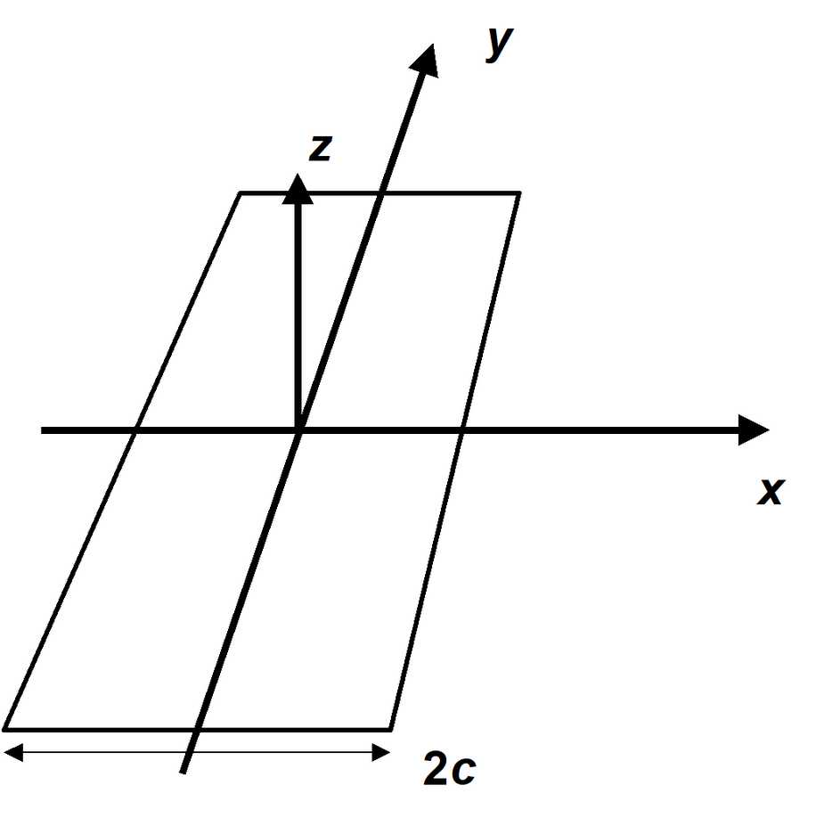
Consider a planar crack with width 2c and length eight times the width.
For such a shape, the aperture (normal displacement or closure) can be determined analytically as (at the mid-section)
δ = 4(1-ν²)/E p√(c²-x²) [6]
where E and ν represent respectively Young's (rock mass scale - deformation) modulus and Poisson's ratio, and p represents the homogeneous pre-mining stress state. The stress ahead of the crack tip can also be determined analytically as
σ = px /√(x²-c²) [7]
The work done in deforming the crack surfaces is equivalent to the total energy released and can be determined as follows (the integral is taken from -c to +c)
W = ½ ∫ pδ dx
= 2π (1-ν²) p²/E ∫ √(c²-x²) dx [8]
= π (1-ν²) p²c²/E
As the length of the crack increases, the energy release per unit length of crack extension can be determined by differentiation as
dW/dc = 2π (1-ν²) p²c/E [9]
For extension of one end of the crack only, we obtain the energy release rate as half this value
ERR = π (1-ν²) p²c/E [10]
Comparison with Planar Crack Solution
If we now compare the planar crack geometry with the crack-tip formulation, it can be observed that for planar crack (comparing equations [1] and [2] with [6] and [7])
pδ = 4(1-ν²)/E p√(2c) [11]
pσ = p√(c/2) [12]
Observation of these equations reveals that these two parameters can be related in the case of a planar crack geometry by
pδ = 8(1-ν²)/E pσ [13]
Substituting these into equation [5] for ERR provides
ERR = π (1-ν²) p²c/E [14]
the same result as determined for the planar crack (equation [10]).
Various substitutions for pδ and pσ can be made to determine
ERR = 2π (1-ν²) π pσ²/E [15]
and
ERR = 1/32 π pδ² E/(1-ν²) [16]
This later equation is the same expression derived by Ryder and Jager (their equation [11], p. 236, Rock Mechanics for Tabular Hard Rock Mines, 2002). They state that this equation is used to calculate ERR in MINSIM. Some form of α-edge correction (Ryder and Napier, Numerical Methods in Geomechanics, Nagoya, 1985) is also apparently implemented but the details on exactly how this done are unclear.
ERR Calculation in Map3D
Both of pδ and pσ can be determined from numerical modelling.
For example, given the normal displacement (closure) δm determined at distance a behind the advancing face, pδ can be determined using equation [1] as
pδ = δm /√a [17]
Similarly, given the stress σm at distance b ahead of the advancing face, pσ can be determined using equation [2] as
pσ = σm √b [18]
Note that there is no reason for a to be equal to b and hence there is no requirement for uniform boundary element sizes.
Once either or both of pδ and pσ are determined, ERR is readily calculated from equation [5], [15] or [16].
Detailed studies of stress and displacement distributions near the crack tip reveal that for constant DD elements, both the aperture and stress are consistently over-estimated. Fortunately, the degree of over-estimation is closely related to the element size and it can be found that if a is multiplied by 3/2 and b is multiplied by 2/3, much more accurate results can be obtained. With these substitutions, and using equation [17] and [18], ERR can be determined from
ERR = 1/6 π δm σm √(2/3 b) / √(3/2 a)
= 1/6 π δm σm √(b/a) [19]
This equation is used to calculate ERR in Map3D.
An Example
With E of 60000 MPa, ν of 0.25, p of 100 MPa and c of 100 m we calculate theoretical values for pσ of 707.11, pδ of 0.088388 and 49.1 MN/m for ERR
This can be modelled using Map3D using uniform elements of width w, to provide the following results:
Note that the stress σm and normal displacement (closure) δm are determined at the element centres. Since uniform element widths were used, a equals b equals ½w
|