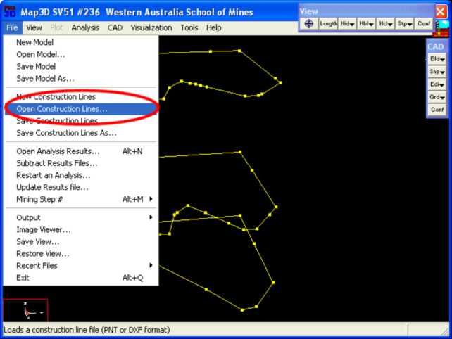
Step 1: Import digitized mine plans.
•The plans for this example are in a file called "bulk.dxf".
•These are imported using the File > Open Construction Lines command.
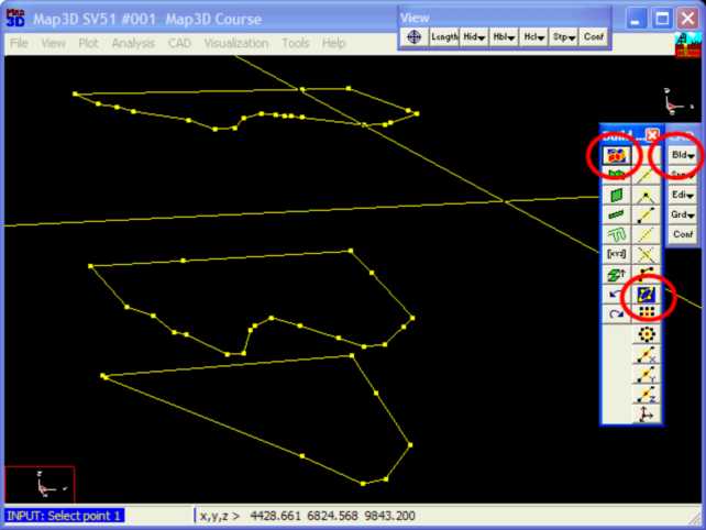
Step 2: Next we start the FFLoop routine and set the CLoop snap mode.
•FFLoop can be started by selecting ![]() then
then ![]() (CAD > Build > FFLoop).
(CAD > Build > FFLoop).
•CLoop snap mode can be set by selecting ![]() (CAD > Snap > Trace CLoop).
(CAD > Snap > Trace CLoop).
Step 3: Build the FFLoop.
•The FFLoop is built by selecting one points on each construction line.
•Note that points are automatically be generated at 10m intervals along long sides
•It is best to pick points that are at sharp corners or bends as the line between the loops will guide the construction process.
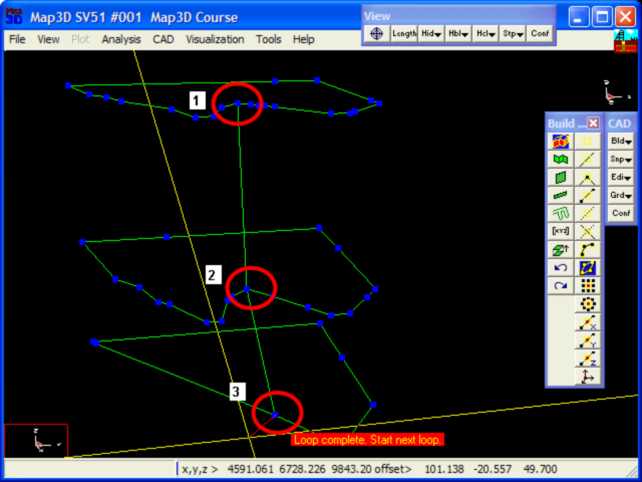
Step 4: Signal completion of construction.
•Now that all of the loops have been defined, we pick ![]() (CAD > Build > FFLoop) again to signal completion of construction.
(CAD > Build > FFLoop) again to signal completion of construction.
•This can also be signalled by picking the last point (i.e. point 3) a second time.
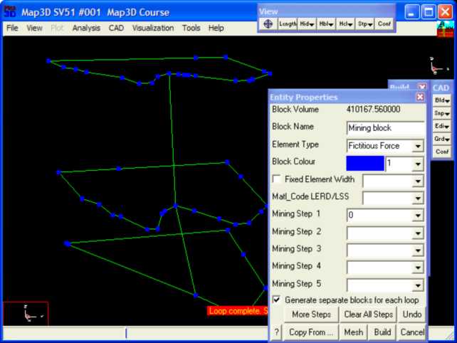
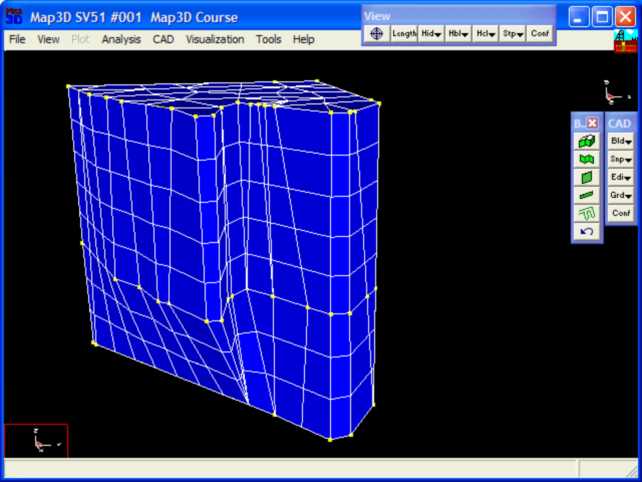
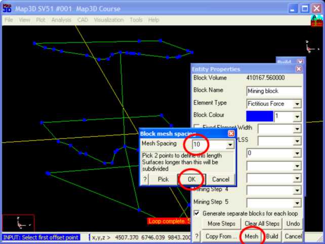
Step 5: Build the stope.
•The FFLoop can now be built using the ![]() function.
function.
•Specify 10 for the Mesh Spacing then pick OK.
Step 6: Construction Complete.
•This completes construction of the stope.