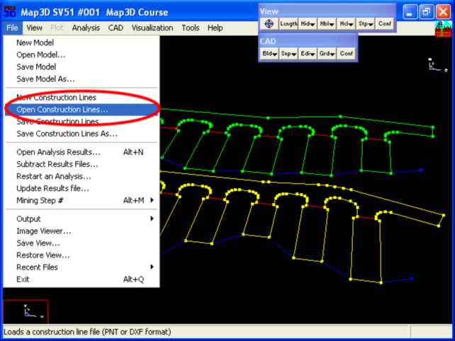
Step 1: Import digitized mine plans.
•The plans for this example are in a file called "bulk.dxf".
•These are imported using the File > Open Construction Lines command.
Step 2: Next we start the FFLoop routine and set the CLoop snap mode.
•FFLoop can be started by selecting ![]() then
then ![]() (CAD > Build > FFLoop).
(CAD > Build > FFLoop).
•CLoop snap mode can be set by selecting ![]() (CAD > Snap > Trace CLoop).
(CAD > Snap > Trace CLoop).
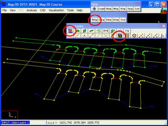
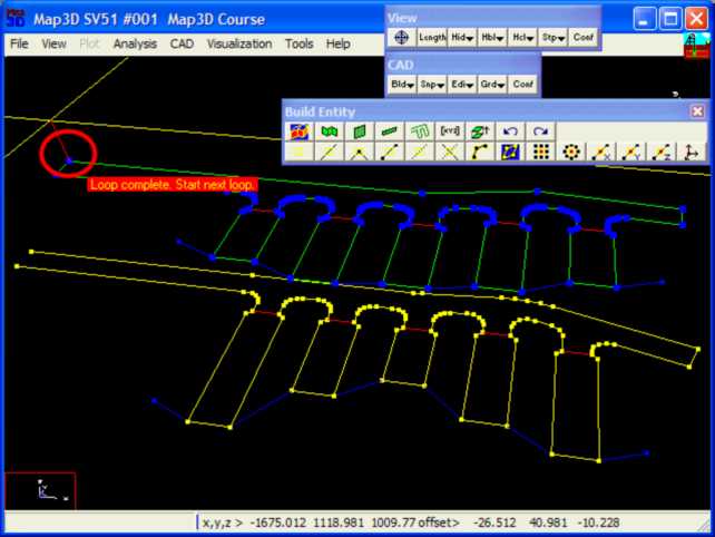
Step 3: Build the FFLoop.
•The FFLoop is built by selecting one of the points on the desired construction line.
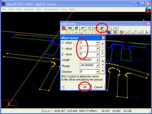
Step 4: Extrude the floor plan into a 3D drift.
•At this point we have constructed the floor plan of the drift.
•This can now be extruded into a 3D shape by picking ![]() (CAD > Build > Offset/Extrude).
(CAD > Build > Offset/Extrude).
•Set the offset vector to (0 0 5).
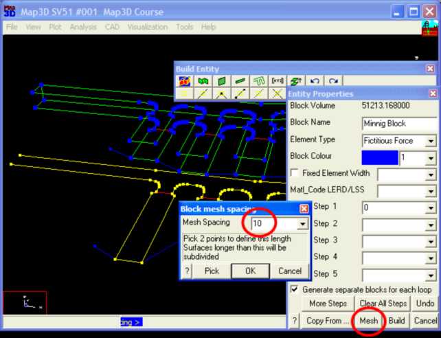
Step 5: Build the drift.
•The FFLoop can now be built using the ![]() function.
function.
•Specify 10 as the Mesh Spacing, then press OK.
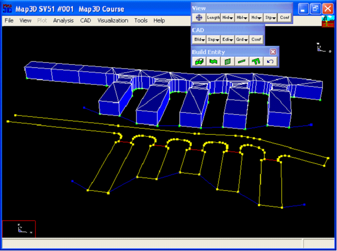
Step 6: Construction Complete.
•This completes construction of the drift.