![]() Plot > Strength Factors > In-plane Parameters
Plot > Strength Factors > In-plane Parameters
|
|
Top Previous Next |
|
Sets up the strength parameters for generating strength factor contour plots in terms of in-plane stress components. These components can be accessed via the Strength Factor Components toolbar as follows:
This toolbar can be changed to a vertical orientation by dragging is against either the right or left hand edge of the main window. It can be changed back to a horizontal orientation by dragging is against either the top or bottom edge of the main window.
Selecting the
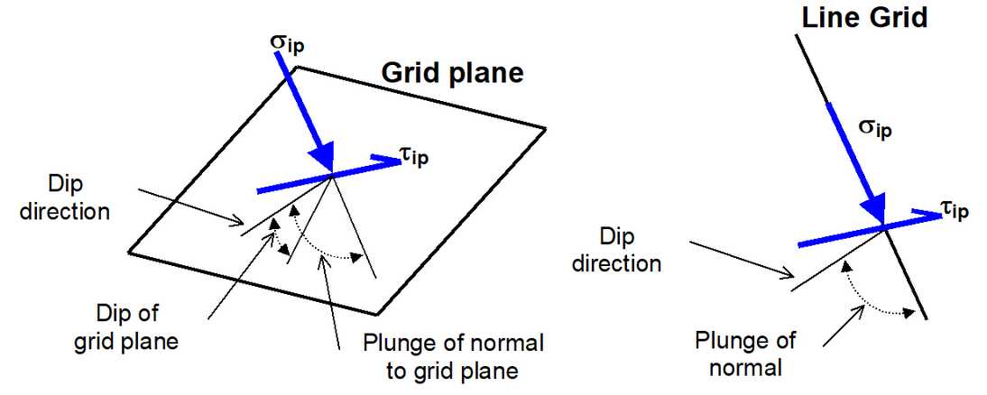
To calculate the in-plane shear and normal stresses, the stress state at each point on the grid plane is reoriented to determine the maximum shear stress parallel to the grid plane and the stress normal to the grid plane.
In elastic analysis the maximum in-plane shear and normal stresses can be used with the Mohr-Coulomb strength criterion to estimate the amount of slip due to over-stressing, on a fault, joint set or bedding plane oriented in the same way as the grid plane. Since these parameters are orientation dependant, this criterion is representative for anisotropic rock mass stability.
By contrast, in non-linear analysis the stresses can never exceed the strength unless some creep is used. In this latter case, viscous creep can allow stress states above the failure criterion, thus indicating a lack of static equilibrium. Hence for non-linear analysis one normally directly considers the amount of non-linear strain or the strain rate predicted by the model
Backfill-Hyperbolic in DD planes
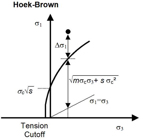
The Mohr-Coulomb criterion defines the shear strength in terms of shear stress and normal stress as follows:
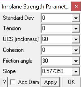
Tension cutoff, UCS and Cohesion are specified in units of stress (MPa or psi).
Friction angle is specified in degrees.
Standard Deviation specifies the uncertainty you have in the failure criterion measured in the τip direction (specified in units of stress, MPa or psi).
Acc Dam – plots accumulated damage. Refer to Accumulated Damage
Apply – regenerates the contour plot.
Related topics:
|