Hyperbolic-Backfill material can be used to describe non-linear response in DD planes in both Map3D Fault-Slip, Map3D Non-Linear and Map3D Visco-Plastic.
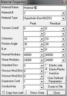
Material Name - specifies a descriptive name for the material.
Material # - specifies the material number.
•Material #1 is reserved for the host material.
•Other material numbers are used to define alternate material zones such as ore, fault gouge, backfill etc.
Material Type - specifies the material type (Mohr-Coulomb, Hoek-Brown, Drucker-Prager, Fault-Gouge, Hyperbolic-Backfill, Quadratic-Backfill, Equilibrated-Gouge, Yielding-Pillar or none).
•Hyperbolic-Backfill - defines the failure envelope as a straight line in the same as Mohr-Coulomb in DD planes but without UCS.
•Strength is defined in terms of in-plane shear and normal stresses as follows:
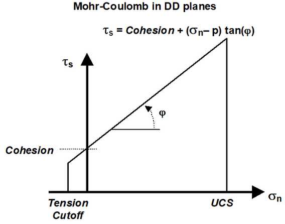
•Tension Cutoff and Cohesion are specified in units of stress (MPa or psi).
•Friction angle and dilation angle are specified in degrees.
•Cohesion and friction angle define the shear response.
•The tension cutoff defines the response in the direction normal to the shear plane.
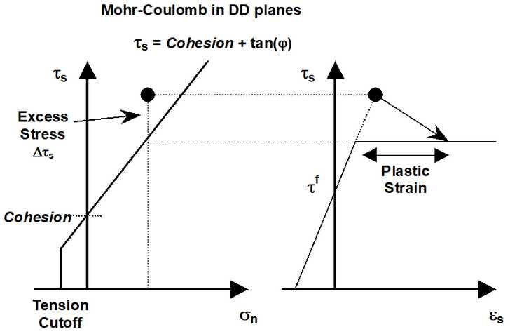
•Peak values of these parameters are used up until failure.
•After yielding, the residual values are used to provide a strain softening response.
•Residual values are ignored in elastic analyzes.
•If fluid pressure is specified as part of the Stress State, the effective normal stress (σn-p) is used (here p is the fluid pressure).
B, et - for DD planes the Hyperbolic-Backfill criterion defines the hyperbolic normal response as follows:
•The normal stress varies according to the hyperbolic relation.
•As the strain approaches the value B the normal stress rapidly become infinite thus limited the amount of normal displacement (closure) that can take place.
Normal and Shear Modulus - specify moduli in units of stress (MPa or psi).
•The normal response is defined above. N represents the value of the normal stress (for σf=0) at εn=½(εt+B).
•The shear stresses acting on the surfaces of the elements are related to the elastic portion of the shear displacement (ride) through the shear modulus as in the Fault-Gouge model.
Standard Deviation - specify standard deviation in units of stress (MPa or psi).
•This parameter describes the uncertainty you have in the strength parameters.
•This parameter is only used for plotting the probability of shear failure Plot > Strength Factors > In-Plane Probability N-distribution.
Viscous Modulus (Gn and Gs) - These parameters are used only in non-linear analyzes (3D FF blocks in Map3D Non-Linear and DD planes in Map3D Fault-Slip).
•The viscous modulus describes the creep response. where the creep resistance is determined as the creep coefficient C, times the plastic strain rate. Note that the user must select both the creep coefficient C, and the time step size Δt, then specify the quotient of these as the viscous modulus G.
•Gn is not used in the hyperbolic model.
•Specify the viscous modulus in units of stress (MPa or psi).
Expansion Coefficient and Conductivity are only used in Map3D Thermal-Fluid Flow.
• Map3D Thermal-Fluid Flow can be used to simultaneously solve steady state heat/fluid flow coupled to the stress analysis.
Elastic only - when checked this material will respond elastically only, i.e. strength parameters will not be used.
•This can be used to define zones with different elastic properties and/or initial stress states. This could include for example stiff dykes, soft ore zones, backfill or support elements.
Elasto-Plastic - when checked this material will respond elasto-visco-plastically, i.e. the strength parameters will be used as a flow rule.
•This can be used to define zones with both different elastic properties and strength parameters.
•Note that in Map3D Fault-Slip, only DD elements (i.e. fault gouge) are permitted to respond non-linearly.
•In Map3D Non-Linear and Map3D Visco-Plastic the 3D rock mass can also yield plastically.
Inactive - when checked this material will not be used in the stress analysis and hence will not affect the predicted stresses, strains or displacements.
•This can be used to define zones with different strength parameters to be used when generating contours of strength factors.
User Defined - allows specification of user defined parameters to be used in contouring.
•Different parameters are defined for each material number.
•These parameters are used with ![]() Plot > Stress > User
Plot > Stress > User
•This can be used to define zones with different strength parameters to be used when generating contours of strength factors.
Dump to File - allows you to dump all material property data to a file for viewing in Notepad or Excel.
Copy from material - allows you to copy the material properties from one material number to another. All properties including the stress state are copied.
Stress State - specifies the initial (far field) stress state for the material.
•Most materials are inserted into blocks with the same (far field) stress state.
•Materials such as props or backfill are placed at near zero initial stresses.
Over-stressing can be presented in several ways including:
![]() Plot > Strength Factors > dTip In-Plane excess shear stress
Plot > Strength Factors > dTip In-Plane excess shear stress
![]() Plot > Strength Factors > dTub Ubiquitous-plane excess shear stress
Plot > Strength Factors > dTub Ubiquitous-plane excess shear stress
![]()
![]() Plot > Strength Factors > SF-ip Strength/Stress
Plot > Strength Factors > SF-ip Strength/Stress
![]()
![]() Plot > Strength Factors > SF-ub Strength/Stress
Plot > Strength Factors > SF-ub Strength/Stress
By contrast, in non-linear analysis the stresses can never exceed the strength unless some creep is used (in this latter case, viscous creep can allow stress states above the failure criterion, thus indicating a lack of static equilibrium). Hence for non-linear analysis one normally directly considers the plastic strain or the plastic strain rate predicted by the model as an indicator of damage.
In DD planes, the elastic strains are determined from the stresses by
τs = τf + Shear Modulus εselastic
σn = σf + Normal Modulus (εnelastic- εt )/( B - εnelastic)
where Shear Modulus and Normal Modulus represent respectively the elastic moduli of the gouge material in the shear and normal directions, and τf and σf represent the initial stress state in the shear and normal directions, and
εselastic = δselastic / Thickness
εnelastic = δnelastic / Thickness
where δselastic and δnelastic represent respectively the elastic component of the shear displacement (ride) and normal displacement (closure) and Thickness represents the DD plane thickness (i.e. fault gouge, seam width, mining width or pillar height). The DD plane thickness is set using
and can be modified using
![]() CAD > Edit > Entity Properties
CAD > Edit > Entity Properties
In DD elements, if the shear stress goes above the strength, the plastic strain can be determined by limiting the stress
τs - τs° - C Δεsplastic /Δt = Cohesion + tan(φ) ( σn - σn° - C Δεnplastic /Δt )
where
τs° = Shear Modulus εsplastic
σn° = Normal Modulus εnplastic
The accumulated plastic strain εplastic, is determined as the sum of the plastic creep increments Δεplastic, for all creep steps.
If the normal stress goes below the tension cutoff, the plastic strain can be determined by limiting the stress
σn - σn° - C Δεnplastic /Δt = To
In the case of shear failure, the plastic normal strain can also have a dilation component
εnplastic = tan(dilation angle) εsplastic
The total strain is equal to the sum of the elastic and plastic parts.
The creep response is simulated using a linear (Bingham) creep model.
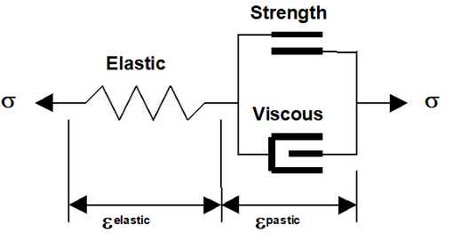
At each creep step the stress state on all yielding elements (elements where the stress exceeds the strength) is calculated as the strength plus the creep resistance
Strength + C Δεnplastic /Δt
C = G Δt
where the creep resistance is determined as the creep coefficient C, times the plastic strain rate. Note that the user must select both the creep coefficient C, and the time step size Δt, then specify the quotient of these as the viscous modulus G. The creep resistance can be used simply as a technique for damping the non-linear deformations or for real time dependent creep simulation
The strains, shear displacement (ride) and normal displacement (closure) can be presented in several ways including:
![]() Plot > Surface > Value > Elastic
Plot > Surface > Value > Elastic
![]() Plot > Surface > Value > Plastic
Plot > Surface > Value > Plastic
![]() Plot > Surface > Value > Total
Plot > Surface > Value > Total
![]() Plot > Strain > E1 - Major principal strain
Plot > Strain > E1 - Major principal strain
![]() Plot > Surface > Es Shear Strain
Plot > Surface > Es Shear Strain
![]() Plot > Surface > En Normal Strain
Plot > Surface > En Normal Strain
![]() Plot > Surface > ds Shear Displacement (Ride)
Plot > Surface > ds Shear Displacement (Ride)
![]() Plot > Surface > dn Normal Displacement (Closure)
Plot > Surface > dn Normal Displacement (Closure)
Also of interest is the plastic creep increment Δεplastic, the contribution to the shear resistance from the viscous element
Δτs = C Δεsplastic /Δt
![]() Plot > Surface > dEs Incremental Shear Strain
Plot > Surface > dEs Incremental Shear Strain
![]() Plot > Surface > dTs Excess Shear Stress
Plot > Surface > dTs Excess Shear Stress
Related Topics: