|
Extrudes a partially constructed entity to assist in generating the remaining points during construction of the following entities:
 CAD > Build > Block CAD > Build > Block
 CAD > Build > FF Loop CAD > Build > FF Loop
 CAD > Build > DD Loop CAD > Build > DD Loop
 CAD > Build > Grid Plane CAD > Build > Grid Plane
 CAD > Build > Grid Line CAD > Build > Grid Line
 CAD > Build > Construction Lines CAD > Build > Construction Lines
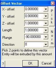
X, Y and Z – offset specify the components of the offset vector. All selected entities will be moved by this amount.
Pick - activates the cursor cross-hairs allowing interactive selection of the offset vector from the model. This requires that you select two points to define this vector.
Length, Plunge and Direction - specify the components of the offset vector. All selected entities will be moved by this amount.
Norm - activates the cursor allowing interactive selection of a surface to make the offset vector normal to. This requires that you select two points to define this vector. Once selected, the components of the offset vector are displayed in the dialogue box.
To assist in visually selecting points from the model, all snap functions are available.
 CAD > Snap CAD > Snap
Once selected, the components of the offset vector are displayed in the dialogue box.
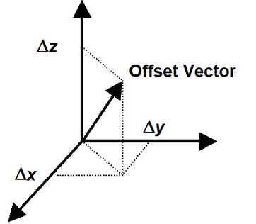
For example if you have constructed the base of a 3D block (points 1, 2, 3 and 4) and you wish to generate the remaining points (5, 6, 7 and 8) at one metre elevation above the base, you would simply enter the offset vector as (0,0,1).
Note that it is possible to create zero volume blocks for example by specifying a zero length offset vector. This allows users to construct individual FF surfaces if desired. While this is permissible it is not recommended as this can lead to unclosed volumes.
|