![]() CAD > Build > DDLoop
CAD > Build > DDLoop
|
|
Top Previous Next |
|
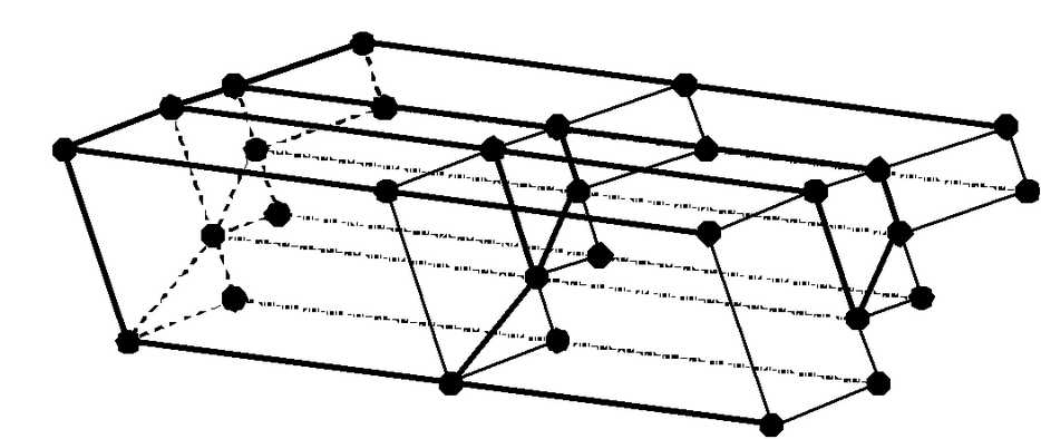
Builds DD (Displacement Discontinuity) type block. These are used for tabular mining, thin seams or fault planes. In all versions of Map3D these zones can yield and behave non-linearly. Multiple DD's can be combined to create complex offset and rolling shapes.
A few examples demonstrating this routine can be found under Model Building Tutorials. Refer specifically to
•Video demo of DDLoop model building with sub-parallel lines •Video demo of DDLoop model building with interior loops
DDLoop
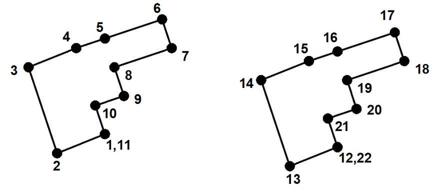
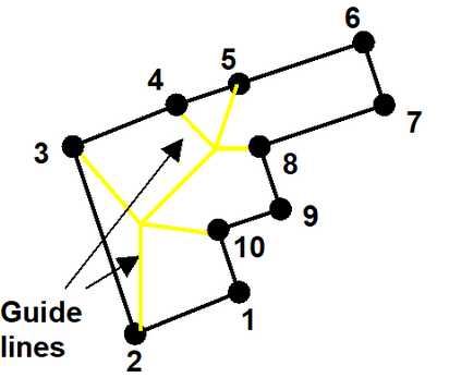
When the routine is initiated the user is prompted to select a series of loops that define the perimeter of the desired zones. The direction you traverse each loop is not relevant. The starting and end point of each loop (e.g. points 1 and 11, or 12 and 22) must be at the same location to define closed loops.
Snap > Trace
Individual points can be selected one at a time, or all points along a construction line segment can be selected using the
Snap > Win
Individual points can be selected one at a time, or all points along multiple construction lines can be selected using the
Close
The DDLoop routine is considered to be complete when one of the following two conditions is met:
•the user selects the final loop point (i.e. point #12,22) a third time
The loops will then be subdivided into a series of 3 or 4 sided DD elements. These surfaces will be further subdivided into boundary elements at a later stage in the program. The routine that does this subdivision searches for corners that are near one another, so the user should take care to define the loop such that the connections are straightforward. In the above example it is recommended that points 4 and 5 be selected or generated.
The Mesh build function (see below) can be used to build the block with surfaces subdivided into smaller parts at the specified block grid spacing. This routine generates interior points as required to maintain well shaped elements.
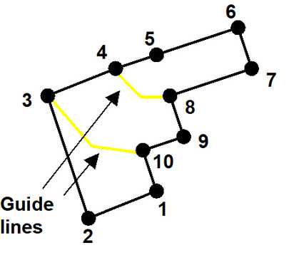
Guide Lines
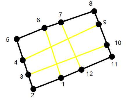
Multiple interior zones can be traced simultaneously by defining guide lines (shown in yellow).
These are simply defined as construction lines. For an example refer to https://www.map3d.com/t.htm. Guide lines must traverse the perimeter loop from edge to edge. Multiple guide lines can be defined that intersect one another thus defining multiple zones.
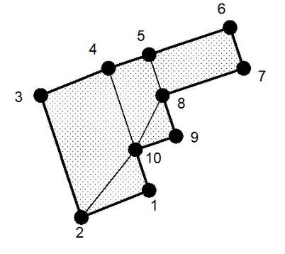
Interior Zones
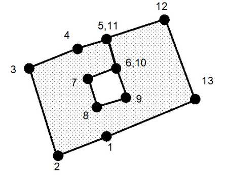
Multiple interior zones (e.g. pillars) can be defined by tracing around their periphery as shown below. The direction you traverse the interior zone is not relevant. As many interior zones as desired can be defined in this way.
Alternatively these interior zones may be conveniently constructed by tracing around the outer perimeter (
Create Zone Blocks - if you are building multi-loop DD planes, you can specify whether or not interfaces will be created between each sub-section so that each sub-section can be treated as a separate group of DDPlanes. Each of these sub-sections will be assigned a different colour number to facilitate easy hiding/unhiding when viewing using Hide Block Colours. If you do not specify this option then a single large group of DDPlanes will be created.
Extrusion using Offset
Once at least two points have been entered, the remaining points can be generated by offsetting the remaining points using
Note also that DD elements can be extruded into FF zones simply by changing the element type from DD to FF.
Miscellaneous
The coordinates of the corners can be typed in from the keyboard
selected by freehand drawing, picked from other entities (other blocks or construction lines) or digitized
A large variety of drawing tools are available to assist in visually selecting points from the model
Corners can be unselected using
Corners can be reselected using
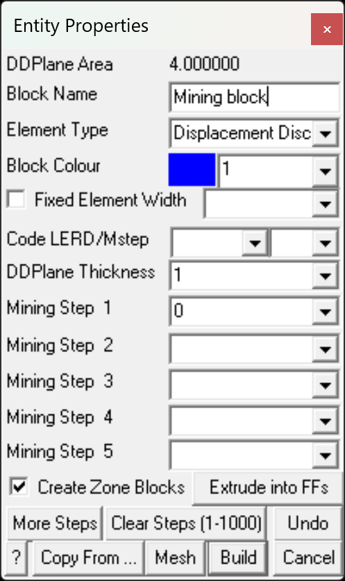
Upon completion of block construction the user is prompted to enter the block properties. This allows you to specify the various parameters including the block colour and mining sequence.
DDPlane Area - displays the combined area of all of the DDPlanes included in the DDLoop.
Block Name - specifies a descriptive name for the block.
Element Type - specifies the type of boundary element that will be used for the block.
•Displacement Discontinuity - DD type elements should be used for tabular mining excavations, fractures and fault planes. •Fictitious Force - FF type elements should be used. For three-dimensional features such as excavations, alternate material zones, back-filled stopes etc. •Inactive elements can be used to display features that are to be included for visualization purposes only and not to be used for the actual stress analysis.
Block Colour - specifies the colour number that will be used to display the block.
Specifies the colour number that will be assigned to each button. A total of 10 colours are available for display. These are numbered respectively
1 through 10, 11 through 20, 21 through 30, etc.,
such that the same colour is displayed for numbers
1, 11, 21..., 2, 22, 32..., 3, 23, 33..., etc.
Fixed Element Width - specifies the user defined element width.
This parameter can be used to force uniform discretization on selected entities. Extreme caution should be used in specifying this value since a small value can easily lead to enormous problem size.
In general this option should not be used (unchecked) and discretization should be left to the AL and AG parameters. These latter parameters will concentrate elements only where analysis results are requested thus optimizing the use of elements and minimizing problem size. For further discussion refer to
CAD > Properties Control Parameters
This parameter can also be used to avoid making surfaces with sides larger than this during the intersection analysis. Any surfaces whose side length exceeds this dimension will not be collapsed
During the discretization process, any surface whose side length exceeds this dimension will be subdivided to prevent surfaces having sides larger than this.
For an example of the use of this parameter refer to Tabular Mining Example
Matl_Code LERD/MStep - specifies the material code that will be substituted into the block for the LERD/LSS calculation.
The first box is for the material code. The second box is to specify the mining step number when the calculation is to be done. If this box is left blank then the LERD calculation will be done for all steps.
Analysis > Options > LERD/LSS.
DDPlane Thickness - specifies the thickness of the material inserted into the DD element (i.e. fault gouge, seam width, mining width or pillar height).
Normal displacement (closure) of the feature when in-filled will be limited to this thickness. Also, the normal displacement (closure) and shear displacement (ride) are divided by the thickness to determine the strain occurring in the in-filling material
Backfill-Hyperbolic in DD planes
Equilibrated-Gouge in DD planes
This parameter should be specified in the same units used to specify the coordinate positions (e.g. metres or feet).
Mining Step n - specifies the material code that will be used for this block in mining step n. In the above example, the block is non-existent at step 1, has material #2 (Ore) inserted in it at step 2, it is excavated at step 3 (material code 0 means to excavate), and finally at step 4 material #5 (backfill) is inserted. When you use a positive material number, the material is placed into the block at the specified initial stress state, and is then allowed to deform according to the elastic/plastic properties you have set for that material number. When you use a negative material number, the material is placed into the block at the specified initial stress state, but the stress state is held at these vales regardless of the deformations, thereby providing a stress boundary condition.
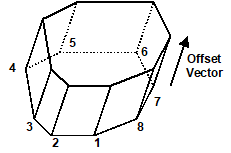
Extrude into FFs - allows you to extrude a DD plane into an FF block. You will be prompted for the extrusion vector
More Steps - allows specification of additional mining steps.
Clear All Steps - clears all mining steps (1-1000).
Undo - unselects the last point entered and returns to the block construction routine
Copy From… - allows you to select another block to copy the entity properties from.
Mesh - builds the block with surfaces subdivided into smaller parts at the specified block grid spacing. This routine generates interior points as required to maintain good shaped elements.
Build - completes block construction and enters the block into the model database.
Once you have completed this operation you have one last chance to undo this and remove this block from the model database by selecting
Cancel aborts block construction.
Note that it is possible to create zero volume blocks for example by specifying a zero length offset vector. This allows users to construct individual FF surfaces if desired. While this is permissible it is not recommended as this can lead to unclosed volumes.
DD blocks can be extruded into 3D FF blocks at any time simply by changing the element type
In this case corners 1 through 8 define the base of the block. The top and sides are automatically generated during the extrusion process.
Note that it is possible to create zero volume blocks for example by specifying a zero length offset vector. This allows users to construct individual FF surfaces if desired. While this is permissible it is not recommended as this can lead to unclosed volumes.
Notes:
Different colour numbers should be used to represent logical groupings of blocks (e.g. for different levels, sections or logical mining units such as development, stoping etc.). These colours are user definable
Any blocks with the same colour number will be automatically combined into single complex shapes by Map3D.
Since it is easy to toggle on and off the display of specific block colour numbers
This provides an efficient method to work with complex model data.
For discussion on model building aspects refer to:
For tutorials on model building refer to:
Pressing the space-bar automatically activates the lat build function that was used. |