|
Top Previous Next |
|
Builds a Tunnel (FF - Fictitious Force type block). This is used to construct a 3D tunnel by extruding a cross-section along the tunnel path. The tunnel surfaces will be further subdivided into boundary elements at a later stage in the program.
Tunnel
Tunnel building proceeds in three stages: 1)Select the tunnel profile; 2)Select the tunnel reference point; 3)Select the tunnel path/layout.
Stage 1 - Tunnel Profile
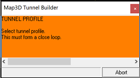
When the routine is initiated the user is prompted to select a tunnel profile:
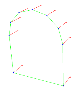
•this must form a closed loop •this can be constructed at any desired orientation (x-y, y-z, x-z or any user defined orientation) onote that if the profile is constructed in the x-y plane, the y-direction will be used as upwards ootherwise if the profile is constructed in the y-z or x-z plane, the z-direction will be used as upwards •when selecting this, keep in mind that this tunnel profile will be extruded away from your point of view (as shown by the red arrows below) •this can be selected as a series of points in a manner similar to how you select construction lines •alternatively, a shape that has been predefined with construction lines can be selected using for example •all snap and build functions can be used during profile section including
Here a tunnel profile is shown in green. The red arrows show the direction in which the tunnel will be extruded during stage 3 - tunnel path/layout.
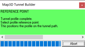
Map3D will detect a completed tunnel profile when the loop is closed. You will then be directed to stage 2 - tunnel reference point.
Stage 2 - Tunnel Reference Point
The tunnel reference point represents the location on the tunnel profile that will be used to locate the profile on the tunnel path/layout. Below, the lower right hand corner has been selected as the reference point.
Upon selecting the reference point, you will be directed to stage 3 - tunnel path/layout. Note that if the wrong reference point is selected, simply undo the selection using either
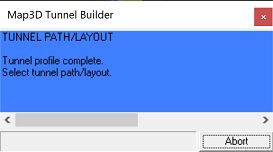
Stage 3 - Tunnel Path/Layout
The tunnel path/layout can now be selected:
•the profile selected above will be extruded along the path/layout •the path/layout can be selected in a manner similar to how you select construction lines •alternatively, the path/layout can be selected along a set of predefined construction lines •closed tunnel loops are acceptable •inclined tunnel paths are acceptable •all snap and build functions can be used during profile section including
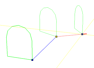
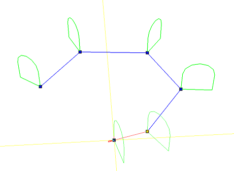
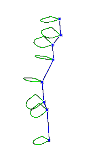
Above on the left, the first two points on the path have been chosen in the horizontal plane (inclined or declined less than 45°), hence the tunnel is extruded as a horizontal drive with the section oriented vertically as shown. On the right, the first two points on the path are chosen in the vertical plane (inclined or declined more than 45°), hence the tunnel is extruded as a vertical shaft with the section oriented near horizontally as shown.
The tunnel path/layout is considered to be complete when one of the following two conditions is met:
•the user selects the final point a second time
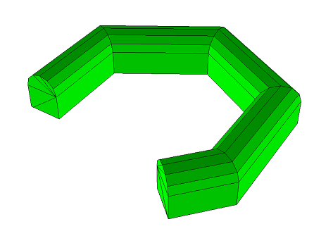
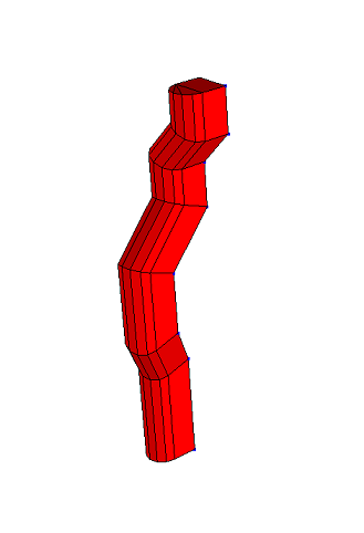
Upon completion, the tunnel will then be constructed as shown below.
Miscellaneous
The coordinates of the corners can be typed in from the keyboard
selected by freehand drawing, picked from other entities (other blocks or construction lines) or digitized
A large variety of drawing tools are available to assist in visually selecting points from the model
Corners can be unselected using
Corners can be reselected using
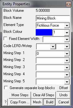
Upon completion of block construction the user is prompted to enter the block properties. This allows you to specify the various parameters including the block colour and mining sequence.
Block Volume - displays the volume of the block.
Block Name - specifies a descriptive name for the block.
Element Type - specifies the type of boundary element that will be used for the block.
•Fictitious Force - FF elements should be used for three-dimensional features such as excavations, alternate material zones, back-filled stopes etc. •Inactive elements can be used to display features that are to be included for visualization purposes only and not to be used for the actual stress analysis.
Block Colour - specifies the colour number that will be used to display the block.
Specifies the colour number that will be assigned to each button. A total of 10 colours are available for display. These are numbered respectively
1 through 10, 11 through 20, 21 through 30, etc.,
such that the same colour is displayed for numbers
1, 11, 21..., 2, 22, 32..., 3, 23, 33..., etc.
Fixed Element Width - specifies the user defined element width.
This parameter can be used to force uniform discretization on selected entities. Extreme caution should be used in specifying this value since a small value can easily lead to enormous problem size.
In general this option should not be used (unchecked) and discretization should be left to the AL and AG parameters. These latter parameters will concentrate elements only where analysis results are requested thus optimizing the use of elements and minimizing problem size. For further discussion refer to
CAD > Properties Control Parameters
This parameter can also be used to avoid making surfaces with sides larger than this during the intersection analysis. Any surfaces whose side length exceeds this dimension will not be collapsed
During the discretization process, any surface whose side length exceeds this dimension will be subdivided to prevent surfaces having sides larger than this.
For an example of the use of this parameter refer to Tabular Mining Example
Matl_Code LERD/MStep - specifies the material code that will be substituted into the block for the LERD/LSS calculation.
The first box is for the material code. The second box is to specify the mining step number when the calculation is to be done. If this box is left blank then the LERD calculation will be done for all steps.
Analysis > Options > LERD/LSS.
Mining Step n - specifies the material code that will be used for this block in mining step n. In the above example, the block is non-existent at step 1, has material #2 (Ore) inserted in it at step 2, it is excavated at step 3 (material code 0 means to excavate), and finally at step 4 material #5 (backfill) is inserted. When you use a positive material number, the material is placed into the block at the specified initial stress state, and is then allowed to deform according to the elastic/plastic properties you have set for that material number. When you use a negative material number, the material is placed into the block at the specified initial stress state, but the stress state is held at these vales regardless of the deformations, thereby providing a stress boundary condition.
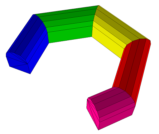
Generate Separate Loop Blocks - You can specify whether or not interfaces will be created between each block so that each block can be treated as a separate mining unit (as shown below). If you do not specify this option then a single large block will be created.
More Steps - allows specification of additional mining steps.
Clear All Steps - clears all mining steps (1-100).
Undo - unselects the last point entered and returns to the tunnel construction routine
Copy From… - allows you to select another block to copy the entity properties from.
Mesh - builds the block with surfaces subdivided into smaller parts at the specified block grid spacing.
Build - completes block construction and enters the block into the model database.
Once you have completed this operation you have one last chance to undo this and remove this block from the model database by selecting
Cancel aborts block construction.
Notes:
Different colour numbers should be used to represent logical groupings of blocks (e.g. for different levels, sections or logical mining units such as development, stoping etc.). These colours are user definable
Any blocks with the same colour number will be automatically combined into single complex shapes by Map3D.
Since it is easy to toggle on and off the display of specific block colour numbers
This provides an efficient method to work with complex model data.
For discussion on model building aspects refer to:
For tutorials on model building refer to:
Pressing the space-bar automatically activates the last build function that was used. |