![]() CAD > Edit > Entity Properties
CAD > Edit > Entity Properties
|
|
Top Previous Next |
|
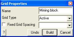
Edit grid name and maximum spacing.
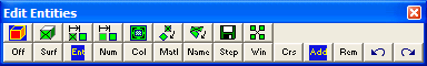
When you initiate this routine you will first be prompted to build a list of entities that you wish to edit
•If Tools > Shift-key Selection is checked, you must hold down the shift key to make multiple selections. •Use of this toolbar is detailed in Build A List of Entities for Editing •Pressing the space-bar automatically activates the last edit function that was used.
Once you have selected the desired entities, you can either pick any of the edit buttons:
•double click on any vertex to execute the highlighted function, •right click for a list of options.
If any of the fields in the dialogue box read "Variable" it is because some of the blocks you have selected have different properties for that field. If you wish to leave these properties as they are (i.e. different for each block), leave the field as "Variable". If you wish to change the value of that field for all selected blocks, enter the desired value.
Name - specifies a descriptive name for the grid.
Grid Type - specifies whether you want the grid to be active (used in the stress analysis) or inactive (not used in the stress analysis).
Maximum Spacing - specifies the maximum spacing permitted. •This parameter can be used to force fine uniform discretization on selected grids. Extreme caution should be used in specifying this value since a small value can easily lead to enormous problem size. •In general this parameter should be left blank (i.e. not used), and discretization should be left to the AG parameter. This latter parameter will concentrate elements only where analysis results are requested thus optimizing the use of elements and minimizing problem size.
CAD > Properties Control Parameters.
•If this field is left blank this parameter is not used.
OK - completes editing of blocks and modifies any properties that have been changed.
Cancel - aborts editing of entities.
Once you have completed any edit operation you have one chance to undo the modifications by selecting
You can also restore the same selection set and modify the same set of entities again be selecting
You can adjust the double click time using
|