Select corners using a window.
This snap mode can be used as a quick method for building DDLoops (![]() CAD > Build > DDLoop), FFLoops (
CAD > Build > DDLoop), FFLoops (![]() CAD > Build > FFLoop), Tunnels (
CAD > Build > FFLoop), Tunnels (![]() CAD > Build > Tunnel), CLines (
CAD > Build > Tunnel), CLines (![]() CAD > Build > CLines) and GLines (
CAD > Build > CLines) and GLines ( CAD > Build > GLines).
Although this snap mode is most often used to select multiple points along CLines, corners are permitted to be located on all element types including: FF elements, DD elements, GPlanes, GLines and CLines.
•Video Demo of FFLoop Model Building
•Video Demo of DDLoop model buiding
•Video Demo of Model_Simplification_Using_Slicing
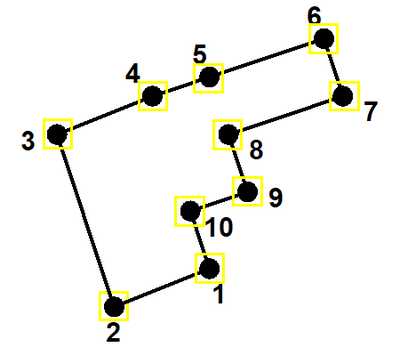
In the figure above, if you pick one or more points prior to selecting a window, the windowed points will be added to those existing points, starting with the nearest previously selected point.
For example if you were to pick point 3 prior to selecting a window, then use a window including points 4, 5, and 6 would add those points in that order.
Alternatively if you were to pick point 3 prior to selecting a window, then use a window including points 1, 2, and 10 would add those points in the order 2, 1 then 10.
In the figure above, if you do not pick one or more points prior to selecting a window, the windowed points will selected starting at locations as far as possible apart.
For example if you were select a window over all of the points, since points 2 and 6 are furthest apart, then points would be selected as 2, 3, 4, 5, 6, 7, 8, 9, 10, 1, 2.
As this example forms a closed loop, the points are selected as such.
This forms a loop suitable for DDLoop construction (![]() CAD > Build > DDLoop).
CAD > Build > DDLoop).
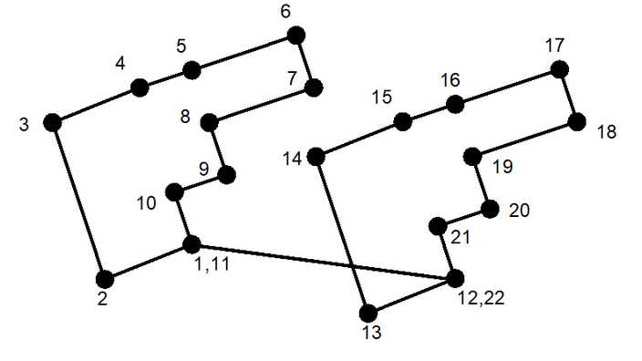
In the figure above, if you pick point 1 prior to selecting a window, then use a window including all points, then all of the points will be selected as shown:
1, 2, 3, 4, 5, 6, 7, 8, 9, 10, 11, 1, 12, 13, 14, 15, 16, 17, 18, 19, 20, 21, 22, 12.
This forms two loops suitable for FFLoop construction (![]() CAD > Build > FFLoop).
CAD > Build > FFLoop).
Alternatively if you were to pick point 3 prior to selecting a window, then use a window including points 1, 2, and 10 would add those points in the order 2, 1 then 10.
Notes:
The location of all points along construction lines can be viewed by setting the View > Render > Cline dot radius parameter.
Before using this trace snap mode, construction lines should be cleaned up using the CAD > Pack and Renumber Clines function.
The ![]() CAD > Edit > Smooth Construction Lines function can also be used to aid in cleaning up construction lines.
CAD > Edit > Smooth Construction Lines function can also be used to aid in cleaning up construction lines.