Mohr-Coulomb material can be used to describe non-linear response in 3D FF blocks in Map3D Non-Linear. It can also be used as a failure criterion for elastic analyzes in Map3D Fault-Slip.
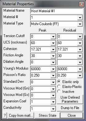
Material Name - specifies a descriptive name for the material.
Material # - specifies the material number.
•Material #1 is reserved for the host material.
•Other material numbers are used to define alternate material zones such as ore, fault gouge, backfill, softened materials etc.
Material Type - specifies the material type (Mohr-Coulomb, Hoek-Brown, Drucker-Prager, Fault-Gouge, Equilibrated-Gouge, Yielding-Pillar, Hyperbolic-Backfill, Quadratic-Backfill, Softened-Material or none).
•Mohr-Coulomb - defines the failure envelope as a straight line.
•For 3D FF blocks the Mohr-Coulomb criterion defines strength in terms of principal stresses as follows:
•Tension cutoff and UCS - are specified in units of stress (MPa or psi).
•Friction angle and dilation angle are specified in degrees.
•Cohesion is related to UCS and friction angle by the relationship UCS=2 Coh tan(45+φ/2). If Cohesion is specified then UCS is determined from this relation.
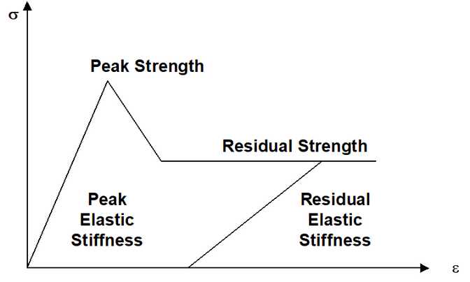
•Peak values of these parameters are used up until failure. After yielding, the residual values are used to provide a strain softening response.
•Residual values are ignored in elastic analyzes.
Young's Modulus and Poisson's Ratio - specify Young's (rock mass scale - deformation) Modulus in units of stress (MPa or psi).
•Peak values of these parameters are used up until failure.
•After yielding, the residual values are used. Residual values are ignored in elastic analyzes.
Standard Deviation - specify standard deviation in units of stress (MPa or psi).
•This parameter describes the uncertainty you have in the strength parameters.
•This parameter is only used for plotting the probability of shear failure Plot > Strength Factors > Rockmass Probability N-distribution.
Viscous Modulus (Gn and Gs) - These parameters are used only in non-linear analyzes (3D FF blocks in Map3D Non-Linear and DD planes in Map3D Fault-Slip). For 3D FF blocks only Gs is used.
•The viscous modulus describes the creep response. where the creep resistance is determined as the creep coefficient C, times the plastic strain rate. Note that the user must select both the creep coefficient C, and the time step size Δt, then specify the quotient of these as the viscous modulus G.
•Specify the viscous modulus in units of stress (MPa or psi).
Expansion Coefficient and Conductivity are only used in Map3D Thermal-Fluid Flow.
•Map3D Thermal-Fluid Flow can be used to simultaneously solve steady state heat/fluid flow coupled to the stress analysis.
Elastic only - when checked this material will respond elastically only, i.e. strength parameters will not be used.
•This can be used to define zones with different elastic properties and/or initial stress states. This could include for example stiff dykes, soft ore zones, backfill or support elements.
Elasto-Plastic - when checked this material will respond elasto-visco-plastically, i.e. the strength parameters will be used as a flow rule.
•This can be used to define zones with both different elastic properties and strength parameters.
•Note that in Map3D Fault-Slip, only DD elements (i.e. fault gouge) are permitted to respond non-linearly.
•In Map3D Non-Linear the 3D rock mass can also yield plastically.
Inactive - when checked this material will not be used in the stress analysis and hence will not affect the predicted stresses, strains or displacements.
•This can be used to define zones with different strength parameters to be used when generating contours of strength factors.
User Defined - allows specification of user defined parameters to be used in contouring.
•Different parameters are defined for each material number.
•These parameters are used with ![]() Plot > Stress > User
Plot > Stress > User
•This can be used to define zones with different strength parameters to be used when generating contours of strength factors.
Dump to File - allows you to dump all material property data to a file for viewing in Notepad or Excel.
Copy from material - allows you to copy the material properties from one material number to another. All properties including the stress state are copied.
Stress State - specifies the initial (far field) stress state for the material.
•Most materials are inserted into blocks with the same (far field) stress state.
•Materials such as props or backfill are placed at near zero initial stresses.
In elastic analysis the principal stresses are normally used with the Mohr-Coulomb or Hoek-Brown strength criterion to estimate the amount of damage due to over-stressing. One can expect that more excess stress in an elastic analysis would in general correlate with increased amounts of plastic strain in a non-linear analysis. Since none of the parameters have any orientation sensitivity, this criterion is representative for homogeneous rock mass stability.
Over-stressing can be presented in several ways including:
![]() Plot > Strength Factors > dS1 - Excess Stress
Plot > Strength Factors > dS1 - Excess Stress
![]() Plot > Strength Factors > dTmax - Excess Stress
Plot > Strength Factors > dTmax - Excess Stress
![]()
![]() Plot > Strength Factor > SF-A - Strength/Stress
Plot > Strength Factor > SF-A - Strength/Stress
![]()
![]() Plot > Strength Factor > SF-B - Strength/Stress
Plot > Strength Factor > SF-B - Strength/Stress
![]()
![]() Plot > Strength Factors > SF-C - Strength/Stress
Plot > Strength Factors > SF-C - Strength/Stress
By contrast, in non-linear analysis the stresses can never exceed the strength unless some creep is used (in this latter case, viscous creep can allow stress states above the failure criterion, thus indicating a lack of static equilibrium). Hence for non-linear analysis one normally directly considers the plastic strain or the plastic strain rate predicted by the model as an indicator of damage.
In 3D FF blocks, the elastic strains are determined from the stresses by
σxx = σxxf + [ (1-ν) εxxelastic + ν ( εyyelastic + εzzelastic ) ] E / [ (1+ν) (1-2ν) ]
σyy = σyyf + [ (1-ν) εyyelastic + ν ( εzzelastic + εxxelastic ) ] E / [ (1+ν) (1-2ν) ]
σzz = σzzf + [ (1-ν) εzzelastic + ν ( εxxelastic + εyyelastic ) ] E / [ (1+ν) (1-2ν) ]
τxy = τxyf + εxyelastic E / (1+ν)
τyz = τyzf + εyzelastic E / (1+ν)
τxz = τxzf + εxzelastic E / (1+ν)
where E and ν represent respectively Young's (rock mass scale - deformation) modulus and Poisson's ratio, and σf and τf represent the initial (pre-mining) stress state
In Map3D Non-Linear, if the stress goes above the strength, the plastic strain can be determined by limiting the stress
σ1 - σ1° - C Δε1plastic /Δt = UCS + q ( σ3 - σ3° - C Δε3plastic /Δt )
where
σ1° = [ (1-ν) ε1plastic + ν ( ε2plastic + ε3plastic ) ] E / [ (1+ν) (1-2ν) ]
σ2° = [ (1-ν) ε2plastic + ν ( ε3plastic + ε1plastic ) ] E / [ (1+ν) (1-2ν) ]
σ3° = [ (1-ν) ε3plastic + ν ( ε1plastic + ε2plastic ) ] E / [ (1+ν) (1-2ν) ]
The accumulated plastic strain εplastic, is determined as the sum of the plastic creep increments Δεplastic, for all creep steps.
If the stress goes below the tension cutoff, the plastic strain can be determined by limiting the stress
σ3 - σ3° - C Δε3plastic /Δt = To
The plastic volumetric strain can also have a dilation component
εvolume = ( ε1plastic + ε2plastic + ε3plastic ) = tan(dilation angle) ε1plastic
The total strain is equal to the sum of the elastic and plastic parts.
The creep response is simulated using a linear (Bingham) creep model.
At each creep step the stress state on all yielding elements (elements where the stress exceeds the strength) is calculated as the strength plus the creep resistance
σ = Strength + C Δεplastic /Δt
C = G Δt
where the creep resistance is determined as the creep coefficient C, times the plastic strain rate. Note that the user must select both the creep coefficient C, and the time step size Δt, then specify the quotient of these as the viscous modulus G. The creep resistance can be used simply as a technique for damping the non-linear deformations or for real time dependent creep simulation
The strains can be presented in several ways including:
![]() Plot > Strain > Value > Elastic
Plot > Strain > Value > Elastic
![]() Plot > Strain > Value > Plastic
Plot > Strain > Value > Plastic
![]() Plot > Strain > E1 - Major principal strain
Plot > Strain > E1 - Major principal strain
![]() Plot > Strain > E2 - Intermediate principal strain
Plot > Strain > E2 - Intermediate principal strain
![]() Plot > Strain > E3 - Minor principal strain
Plot > Strain > E3 - Minor principal strain
![]() Plot > Strain > Emax - Maximum shear strain
Plot > Strain > Emax - Maximum shear strain
![]() Plot > Strain > Evolume - Volumetric shear strain
Plot > Strain > Evolume - Volumetric shear strain
Related Topics:
Drucker-Prager in 3D FF blocks